
Path Validation
Path Validation
Section titled “Path Validation”Path Validation is a crucial feature that checks your FTC autonomous routines for potential issues before you run them on a real robot. It analyzes your paths for collisions with obstacles or field boundaries, and ensures the planned movements are kinematically possible based on your robot's configured constraints.
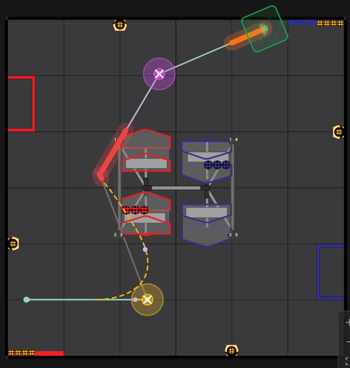
Using the Validation Tools
Section titled “Using the Validation Tools”You can run validation manually or enable it to run continuously in the background.
Manual Validation
Section titled “Manual Validation”To perform a single check of your entire sequence:
- Shortcut:
Shift + V - Command Palette: Open the Command Palette (
Ctrl + P/Cmd + P) and select Validate Path.
When you run manual validation, the visualizer will scan the path and display an alert or overlay indicating any detected issues.
Continuous Validation
Section titled “Continuous Validation”For real-time feedback while you edit, you can enable Continuous Validation.
- Shortcut:
Alt + V - Command Palette: Open the Command Palette and toggle Continuous Validation.
When enabled, the visualizer will constantly check the path as you drag points or adjust headings. This is highly recommended when fine-tuning complex routines around obstacles.
What Validation Checks
Section titled “What Validation Checks”The validation system evaluates your path against five primary check types. Each has custom logic to ensure your robot moves safely and realistically:
1. boundary (Field Boundaries)
Section titled “1. boundary (Field Boundaries)”Ensures the robot does not attempt to drive outside the 144x144 inch field perimeter.
- Validation accurately uses the
LengthandWidthspecified in your Robot Settings to simulate the robot's exact footprint along the entire path, at the angle the robot is actually facing. If any part of the robot's bumper crosses the field wall, it triggers aboundaryerror.
2. obstacle (Obstacles)
Section titled “2. obstacle (Obstacles)”Checks against any custom polygons you have defined in the Obstacles panel.
- If the robot's projected path and physical dimensions intersect with an obstacle polygon, it triggers an
obstacleerror. Collision markers sit at the robot's real position, and thin obstacles that cross the robot are detected.
3. keep-in (Keep-In Zones)
Section titled “3. keep-in (Keep-In Zones)”Special zones where the robot is required to stay inside.
- If the robot's path or footprint exits the boundaries of a designated keep-in zone, it triggers a
keep-inerror.
4. zero-length (Zero-Length Segments)
Section titled “4. zero-length (Zero-Length Segments)”A sanity check that prevents paths from having a distance of zero.
- If a path segment's start point and end point are in the exact same location with no actual movement required, it triggers a
zero-lengtherror, as this can cause mathematical anomalies in the robot's path follower.
5. chain-corner (Chained Corners)
Section titled “5. chain-corner (Chained Corners)”Checks the corners where two chained paths join. A robot can't change direction instantly, so at a sharp corner it carries on past the join, swings out, and steers back onto the next path.
- A corner gets a warning if the direction changes by 60° or more, or if the robot cuts the corner and passes more than 3 inches from the point where the paths join.
- It is an error if the robot is still not back on the next path after it should have settled. This usually means it can't follow the next path at this speed.
- Each corner is reported once. The warning says how far the robot swings or misses by, and appears in the validation list, as a marker on the field, and in Path Statistics (on the Insights tab).
- How strongly the robot corrects depends on Translational P in the Motion settings.
Configuring Validation Settings
Section titled “Configuring Validation Settings”Validation behavior can be customized in the Settings > Robot menu to match your workflow:
- Safety Margin (in): This setting allows you to configure a buffer zone (e.g., 2 inches). Validation will treat obstacles and boundaries as being slightly larger/closer than drawn, giving you a safety buffer against real-world mechanical slop or odometry drift.
- Validate Field Boundaries: A toggle that allows you to completely disable the
boundarychecks. Useful if you are testing isolated movements without worrying about the field walls. - Restrict Dragging: When enabled, this prevents you from manually moving control points or waypoints outside the field boundaries on the canvas.
Resolving Validation Errors
Section titled “Resolving Validation Errors”When an error is detected, the visualizer will typically highlight the problematic segment of the path in red or display warning icons.
Tips for fixing errors:
- Boundary/Obstacle Collisions: Try dragging control points to widen the curve around the obstacle, or use the Path Optimizer (
Ctrl + Shift + O) to let the visualizer find a safe route automatically. - Zero-Length Errors: Delete the redundant path segment or space the points out.
- Chained Corner Warnings: Soften the corner by moving the control points, slow the robot down, or unchain the two paths so the robot stops at the join. The Path Optimizer can also handle sharp chained corners.
Best Practices
Section titled “Best Practices”- Set Accurate Robot Dimensions: Validation is only as good as the data it has. Ensure your robot
LengthandWidthin the Settings menu accurately reflect your real-world robot footprint. - Use Safety Margins: Always set a realistic Safety Margin. A value of
1.5to2.5inches is recommended for most drivetrains.